
Advanced Juniper PoE Debugging
9 April 2020I’ve come across a few instances where I’m troubleshooting WiFi APs that won’t power on or stay powered on. Fortunately, the issues were bad wiring or patch cords, but I did quite a bit of digging into the labyrinth of hamster wheels that make up a Juniper switch and discovered some very low level commands that proved useful. My attempt to document them is below.
In the chassisd log file, have you ever come across something like CHASSISD_UI_POE_ERR: PoE port name mge-0/0/45 status 61 and wondered what the heck “status 61” means? Let’s find out!
I should, at this point, issue a disclaimer. I have no idea what some of the commands available in this “hidden” shell do or what trouble they may cause. There is little to no documentation publicly available, and JTAC didn’t even offer this to me (or know about it?) while I was troubleshooting a PoE issue.
From the CLI of a juniper switch (I’ve tested EX2300C, EX3400, and EX4300 models), enter the following commands:
start shell
su
vty fpc0
Replace fpc0 with the name of the FPC you want to troubleshoot, in the case of a Virtual Chassis.
At this point, your console might begin being spammed by various log messages. Some even are labeled as Error messages, but again, since this isn’t normally exposed to the system logs, I’d offer the advise that they can probably be ignored. (Example, on a switch in front of me, with nothing connected to it at all except a console cable, I’m seeing the message LOG: Err PoE: poe_get_dev_class: Failed to get PD class info – It’s classed as an error, but the switch is perfectly fine…)
The shell here is very basic; there’s no “logging sync” option (a la Cisco) that I’ve found, and the Up/Down keys do not work for command history. Pressing Ctrl-C drops you back to the root shell. But Ctrl-A/E and tab completion do still work, and there is even an inline “?” help function, so it’s not all that bad.
So, let’s find out some more about our PoE issue!
The command that I’m going to be exploring is show poe. This is different from the one normally available in the CLI, and from what I’ve seen, harmless to run on production switches.
TFXPC0( vty)# show poe ?
    device                show poe device information
    port                  show poe port information
    power_bank            show poe power bank
    system                show system information
    version               show poe firmware version
It’s fairly straightforward from here. show poe port 0 status gives you some details about… you guessed it… the PoE status of port 0 on the FPC. Here’s some output from an EX2300C with a NetAlly EtherScope connected and drawing power:
TFXPC0( vty)# show poe port 0 status
As per PD69000 Serial Comm Protocol, version 6.6
Actual Port Status (table 5).
Port Enable = 1
Latch = 0x0
Class = 4
Port is on: Valid Resistor detected.
Port Mode: AF/AT Mode.
Port Operation: 2Pair.
This is what I’d expect to see on a normally working device. The EtherScope is configured as a Class 4 device and is requesting and pulling 25.50 W of power. Let’s have a look at some other commands
TFXPC0( vty)# show poe port 0 measurement
 Vmain Voltage: (0x219), 537 decivolts
 Port Voltage: (0x21c), 540 decivolts
 Calculated Current: (0x1a7), 423 milliamps
 Power Consumption: (0x58ac), 22700 milliwatts
show poe port 0 measurement gets the measurement data from the PoE controller for port 0 every time you execute the command. You can see slight fluctuations in power consumption between consecutive runs of this command. There seems to be a measuring resolution of about 100mW.
The next command is show poe port 0 power_limit. If you’ve configured a maximum-power limit via the CLI, you can see that take effect here. Otherwise, it shows the default limit for the port. Here it is with set poe interface ge-0/0/0 maximum-power 15 configured:
TFXPC0( vty)# show poe port 0 power_limit
Port Power Limit: (0x3b60), 15200 milliwatts
Temporary Port Power Limit: (0x7d00), 15200 milliwatts
Let’s go back up a level. show poe system status gives you some overall health of the PoE controller:
TFXPC0( vty)# show poe system status
CPU Status 1 = 0x0 ; normal.
CPU Status 2 = 0x2
Factory default = 0x0 ; factory default param not set.
GIE = 0x0 ; GIE Normal.
Private Label = 0x1
User Byte = 0xff
Device Fail Status = (0xfc), all devices OK.
Temperature disconnect = (0x0), all devices temperatures ok.
Temperature Alarm = (0x0), all devices temperatures under limit.
Interrupt Register = 0x0

power_consumption = 22
max_shutdown_voltage = 570
min_shutdown_voltage = 440
power_limit = 125
power_bank = 1
Everything looks good there! But what about when things aren’t working so well? Let’s go back to the show poe port 0 status command from earlier:
TFXPC0( vty)# show poe port 0 status
As per PD69000 Serial Comm Protocol, version 6.6
Actual Port Status (table 5).
Port Enable = 1
Latch = 0x0
Class = 4
Port is on: Valid Resistor detected.
Port Mode: AF/AT Mode.
Port Operation: 2Pair.
Port is on: Valid Resistor detected.
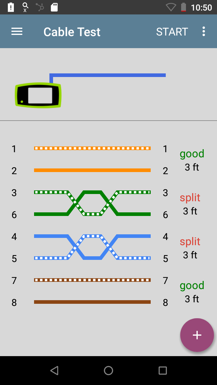
This is the line to watch. With nothing connected to the port, it shows Port is off: detection is in process. Okay, that makes sense. What about when there’s a bad cable? Let’s run the command again with a cable that pins out like this on one end:

I feel so dirty after having made this.
The built-in TDR test on the switch shows the following for this cable with the bad crimp at the far end:
root@bward-sw> request diagnostics tdr start interface ge-0/0/0

Interface TDR detail:
Test status                     : Test successfully executed  ge-0/0/0

{master:0}
root@bward-sw> show diagnostics tdr interface ge-0/0/0

Interface TDR detail:
Interface name                  : ge-0/0/0
Test status                     : Passed
Link status                     : Down
MDI pair                        : 1-2
  Cable status                  : Normal
  Cable length/Distance To Fault: 0 Meters
MDI pair                        : 3-6
  Cable status                  : Cross Talk
  Cable length/Distance To Fault: 3 Meters
MDI pair                        : 4-5
  Cable status                  : Cross Talk
  Cable length/Distance To Fault: 3 Meters
MDI pair                        : 7-8
  Cable status                  : Normal
  Cable length/Distance To Fault: 0 Meters
Polartiy swap                   : N/A
Pair swap                       : N/A
Downshift                       : N/A
The EtherScope even knows something’s wrong, but since I don’t have my wire map dongles with me, it can’t quite figure it out exactly either:
And let’s run the autotest on the EtherScope while it’s connected to the switch and see what happens. Here, hold my beer!
root@bward-sw> show poe interface ge-0/0/0
PoE interface status:
PoE interface                :  ge-0/0/0
Administrative status        : Enabled
Operational status           :   ON
Operational status detail    : IEEE PD Detected
FourPair status              : Disabled
Power limit on the interface : 30.0W
Priority                     : Low
Power consumed               : 22.6W
Class of power device        :        4
PoE Mode                     :   802.3at
TFXPC0( vty)# show poe port 0 status
As per PD69000 Serial Comm Protocol, version 6.6
Actual Port Status (table 5).
Port Enable = 1
Latch = 0x0
Class = 4
Port is on: Valid Resistor detected.
Port Mode: AF/AT Mode.
Port Operation: 2Pair.
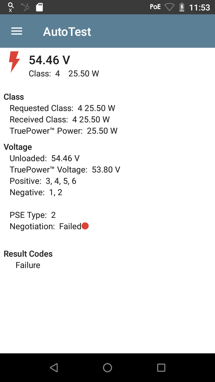
Huh. It linked up at 100mbps and was able to provide power… albeit with a mix of 2 and 4 wires… Messing up cabling is harder than I thought. No wonder we pay contractors so much to do it!
Let’s try again, only this time with a properly pinned-out cable and my UTP strippers slicing part way through the insulation.

Don’t worry little fella… you’ll only feel a pinch…
This results in a test like this, which is sure to cause trouble!
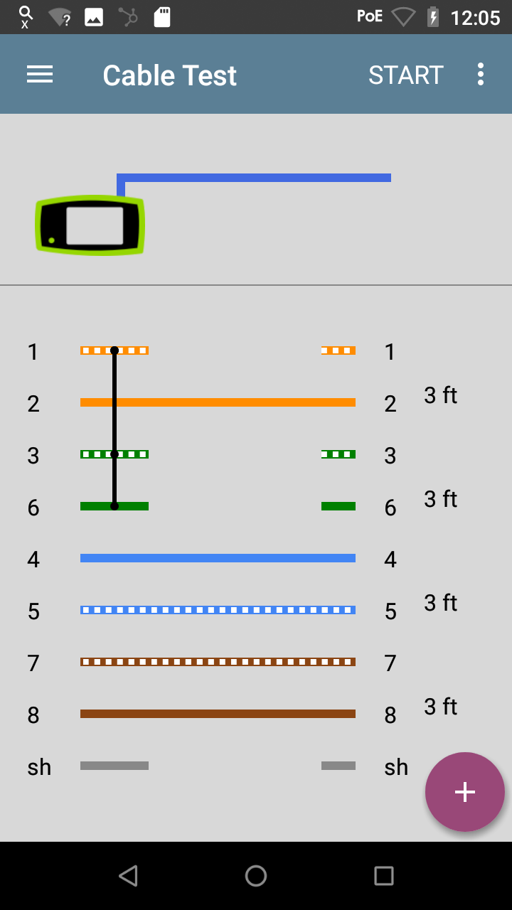
OK, let’s turn on that spot welder switchport…
It linked up at 1gbps, and then I put a little pressure on the UTP strippers to get it to short out. (I think heard a small pop when I did this…)
Running our new command shows the following status:
TFXPC0( vty)# show poe port 0 status
As per PD69000 Serial Comm Protocol, version 6.6
Actual Port Status (table 5).
Port Enable = 1
Latch = 0x20
Short circuit condition.
Class = 4
Port is off : short condition.
Port Mode: AF/AT Mode.
Port Operation: 2Pair.
And the log files show the following messages:
chassisd:
send: yellow alarm set, device PoE, reason PoE Short CirCuit in Interface ge-0/0/0
messages:
bward-sw alarmd[4414]: Alarm set: POE color=YELLOW, class=CHASSIS, reason=PoE Short CirCuit in Interface ge-0/0/0
bward-sw craftd[4440]: Receive FX craftd set alarm message: color: 2 class: 100 object: 152 slot: 0 silent: 0 short_reason=PoE Short Circuit i long_reason=PoE Short CirCuit in Interface ge-0/0/0 id=67109016 reason=33554432
bward-sw craftd[4440]: Minor alarm set, PoE Short CirCuit in Interface ge-0/0/0
Hmm, so no mysterious “status” codes here… I guess they programmed in a human-readable message for a short circuit condition. Again, this is why the contractors make the big bucks. I can’t even replicate a simple wiring screw-up in my home lab…
OK, well, anyway, let’s say that I was able to replicate a wiring condition that the switch didn’t have a human-readable log message for. In the field, I’ve seen CHASSISD_UI_POE_ERR: PoE port name mge-0/0/45 status 61, so let’s pretend I was able to replicate that.
Our new show poe port 0 status command would show something like Power Management-Static -ovl in the output. So, you can therefore deduce that Status 61 == Power Management-Static -ovl! Applying a little engineering translation, this means that there was a static overload condition – more power was drawn from the port than was allowed by its config for more than just a brief burst. Since I was running a Class 4 type device on a port that can actually supply Class 4 power, to me this further translated to damaged insulation, a short circuit (but not bad enough to completely short out), or a bad device on the end. Swapping the end device resulted in the same error, so I was able to further deduce it was a bad wiring job.
Do you wonder what the other statuses mean? (This is the part of the post you might want to bookmark for future reference.) I did some research and found the source of truth for these codes! I list them here for you all to enjoy.
| Hex | Dec | Status | Comment |
| 0x00 | 0 | Port is on: Valid capacitor detected | Legacy PD was detected. |
| 0x01 | 1 | Port is on: Valid resistor detected | 802.3af-compliant PD was detected. |
| 0x02 | 2 | Port is on 4pair | 802.3af/at-compliant PD is powered on 4 pair lines. |
| 0x06 | 6 | Port is off: Main supply voltage is high | Mains voltage is higher than Max Voltage limit |
| 0x07 | 7 | Port is off: Main supply voltage is low | Mains voltage is lower than Min Voltage limit |
| 0x08 | 8 | Port is off: ‘Disable all ports’ pin is active | Hardware pin disables all ports. |
| 0x0C | 12 | Port is off: Non-existing portnumber | Fewer ports are available than the maximum number of ports that the Controller can support. Unavailable ports are considered ‘off’. |
| 0x11 | 17 | Port is yet undefined | Getting this status means software problem. |
| 0x12 | 18 | Port is off: Internal hardware fault | Port does not respond, hardware fault, or system initialization. |
| 0x1A | 26 | Port is off: User setting | User command set port to off. |
| 0x1B | 27 | Port is off: Detection is in process | Interim state during line detection. Status will change after detection process is completed. |
| 0x1C | 28 | Port is off: Non-802.3af powered device | Non-standard PD connected. |
| 0x1D | 29 | Port is off: Overload & Underload states | Succession of Underload and Overload states caused port shutdown. May be also caused by a PD’s DC/DC fault. |
| 0x1E | 30 | Port is off: Underload state | Underload state according to 802.3af (current is below Imin). |
| 0x1F | 31 | Port is off: Overload state | Overload state according to 802.3af (current is above Icut) |
| 0x20 | 32 | Port is off: Power budget exceeded | Power Management function shuts down port, due to lack of power. Port is shut down or remains off. |
| 0x21 | 33 | Port is off: Internal hardware fault | Hardware problems preventing port operation. |
| 0x24 | 36 | Port is off: Voltage injection into the port | Port fails Capacitor Detection due to voltage being applied to the port from external source (in Capacitor Detection mode). |
| 0x25 | 37 | Port is off: Improper Capacitor Detection results | Fail due to out-of-range capacitor value. |
| 0x26 | 38 | Port is off: Discharged load | Port fails Capacitor Detection due to discharged capacitor. |
| 0x2B | 43 | Port is on: Detection regardless (Force On) | Port is forced to turn on, unless system error occurs. |
| 0x2C | 44 | Undefined error during Force On | Reserved for future use. |
| 0x2D | 45 | Supply voltage higher than settings | These errors appear only after port is in Force On. |
| 0x2E | 46 | Supply voltage lower than settings | These errors appear only after port is in Force On |
| 0x2F | 47 | Disable_PDU flag raised during Force On | These errors appear only after port is in Force On |
| 0x30 | 48 | Port is forced on, then disabled | Disabling is performed by the “Set Enable/Disable” command. |
| 0x31 | 49 | Port is off: Forced power error due to Overload | Overload condition according to 802.3af during Force On. |
| 0x32 | 50 | Port is off: “Out of power budget” during Force On | The port is not ON in spite of Force On activation since the maximal power level has been crossed or there is not sufficient |
| 0x33 | 51 | Communication error with PoE devices after Force On | This error appears only after port is forced on. |
| 0x34 | 52 | Port is off: Short condition | Short condition was detected. |
| 0x35 | 53 | Port is off: Over temperature at the port. | Port temperature protection mechanism was activated |
| 0x36 | 54 | Port is off: Device is too hot. | The die temperature is above safe operating value. |
| 0x37 | 55 | Unknown device port status | The device returns an unknown port status for the software. |
| 0x38 | 56 | Force Power Error Short Circuit | Short condition during Force On |
| 0x39 | 57 | Force Power Error Channel Over Temperature | Channel over temperature during Force On |
| 0x3A | 58 | Force Power Error Chip Over Temperature | Device over temperature during Force On |
| 0x3C | 60 | Power Management-Static | Calculated power > power limit |
| 0x3D | 61 | Power Management-Static -ovl | PD class report > user predefined power value |
| 0x3E | 62 | Force Power Error Management Static | Calculated power > power limit during Force On |
| 0x3F | 63 | Force Power Error Management Static -ovl | PD class report > user predefined power value during Force On |
| 0x40 | 64 | High power port is ON | High power device was detected |
| 0x41 | 65 | Chip Over Power | Sum of square currents exceeded SumPowerLimit |
| 0x42 | 66 | Force Power Error Chip Over Power | Same as previous line, during Force On |
| 0x43 | 67 | Port is off: Class Error | Illegal class |
In closing, there’s an awful lot of information to be had from vendor datasheets. In a prior career, I spent many hours pouring through them so I’m no longer overwhelmed by, say, a 98 page document explaining exactly what every pin and memory register on a chip does.
Also, the “vty console” has a ton more commands in it. Hopefully I’ll be able to figure out a use for them and provide some documentation along the way.
Oh, how do you get out of that vty console? Just type exit. That’ll drop you back into the root shell, exit from there into the user shell, and one more exit brings you back to the Junos CLI.
And on what I swear is a totally unrelated note… does anybody want to buy a gently used EX2300C switch??? 🙂
tags: juniper - junos
I certify that none of the text contained within the articles on this site has been generated or edited by any AI technology. I've been a fan of the em dash for many years and am known to use big words from time to time.
This page uses cookies — if that's a problem, then don't use the Internet.
Copyright © Bryan Ward